ArticlesInside MicrofiltersTypes of Cable Extension Wiring Knowledge BaseHow To GuidesDownloadsDriversFirmware Updates Utilities Documentation Contact Support |
UK telephone extension wiringWhere it all startsThis article explains how to wire UK telephone extensions. Early telephone installations were hardwired by a GPO engineer. The line would typically be connected to a master junction box and all telephones would be directly connected. In some rare instances a jack socket may be installed to allow the telephone to be relocated. This type of installation is not suitable for ADSL as it is not possible to install microfilters. If your telephone installation is a hardwired system then the chances are you are still renting your telephone from BT. The installation must not be modified and should ideally be replaced by a modern BT Master Socket. If you are considering installing a master socket yourself, you should be aware that you would breach the terms of your licence from the telephone provider. If an engineer visits to repair a fault and discovers you have made unauthorized changes to the line you may be charged.
Types of cableThere are considerable differences in the types of cable used for wiring telephone extensions. Many low cost extension kits from DIY shops and electrical retailers use low cost, low quality general purpose signal wire. This type of cable is used mainly for alarm installation and is not recommended for extensions that will be used on an ADSL enabled line. The reason being that the typical low cost cable is straight cable that has no protection from interference. There are a great deal of possible sources of interference in the home or office so it is far better to use cable that has some way of reducing interference. It is often said that your telephone wire has traveled hundreds possibly thousands of meters from the exchange so an extra 10 meters in your home or office is not going to make the slightest difference to the performance of the line. What people fail to realize is that the cable from the exchange to the master socket is all twisted pair, by twisting wires in to a pair interference is significantly reduced. It is therefore advisable to use a twisted pair cable to the BT CW1308 standard or better. Standard Category 5 or Category 6 network cable can be used if available, however the large diameter of network cable may make it less than ideal around the home. Connecting coloursThe standard telephone extension wiring is installed using 4 wires although only 3 are actually used. The 4 wires are arranged in to 2 pairs. The blue pair usually consisting of a blue wire with white rings and a white wire with blue rings carries the main telephone signal. One of the wires from the Orange pair is used to carry the ring signal.
|
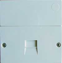
 You are allowed to install extension wiring so long as
the connection to the master socket is via the special terminals provided
on the lower section. When the front screws are removed from the NTE5
the complete lower portion of the socket can
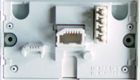
be taken off. On the back of this lower section are the IDC or
screw terminals for extension
wiring. The lower section is connected to the back of the box using
a plug built-in to the panel. The
built-in plug is a standard BT plug and the socket in the box is a standard
BT style socket. This arrangement means that all the internal wiring
can be easily disconnected for fault finding. The socket in
the back of the box can then be used to test
if the line is working. When calling BT to report a fault they will often
advise that you remove this lower section and connect a phone to the
test the line before sending an engineer. It is a good idea to follow
the advice as if a fault turns out to be your own wiring or telephone
equipment you may be charged for the engineer visit.
You are allowed to install extension wiring so long as
the connection to the master socket is via the special terminals provided
on the lower section. When the front screws are removed from the NTE5
the complete lower portion of the socket can
be taken off. On the back of this lower section are the IDC or
screw terminals for extension
wiring. The lower section is connected to the back of the box using
a plug built-in to the panel. The
built-in plug is a standard BT plug and the socket in the box is a standard
BT style socket. This arrangement means that all the internal wiring
can be easily disconnected for fault finding. The socket in
the back of the box can then be used to test
if the line is working. When calling BT to report a fault they will often
advise that you remove this lower section and connect a phone to the
test the line before sending an engineer. It is a good idea to follow
the advice as if a fault turns out to be your own wiring or telephone
equipment you may be charged for the engineer visit.